Introduction to Thin-film Processes
Thin-film deposition is a fundamental step in the fabrication process of micro/nano devices. A thin film is typically less than 1000 nano-meters in thickness. The deposition process begins with the emission of particles from a source (heat, high voltage, etc.). Subsequently, the particles are transported to the substrate. Finally, the particles condensate on the surface of the substrate. The two main deposition methods used today are chemical vapor deposition and physical vapor deposition. This particular article will focus on electron-beam evaporation for thin-film deposition.
In the chemical vapor deposition process, reactant gases are introduced in a chamber and chemical reactions occur on the wafer surface. This, in turn, leads to the formation of a solid film. Chemical vapor deposition, which includes plasma-enhanced chemical vapor deposition, is most commonly used to deposit dielectrics such as silicon dioxide and silicon nitride. On the contrary, physical vapor deposition does not involve chemical reactions. In this process, vapors of constituent materials are created inside the chamber. Condensation then occurs on the wafer surface leading to a solid film. Common types of physical vapor deposition include evaporation deposition and sputtering deposition. Physical vapor deposition is typically used to deposit metals. However, utilizing electron-beam evaporation, oxides and semiconductors can also be deposited. In fact, electron-beam evaporation is the standard technique used to deposit anti-reflective coatings.
Evaporation Methods
As mentioned above, there are two types of physical deposition techniques (sputtering and evaporation). Thermal evaporation, electron-beam evaporation, and inductive heating are the three types of evaporation deposition techniques.
Inductive Heating
Inductive heating involves RF power running through a metal element wound around a crucible. RF induces eddy currents in the charge and causes the crucible to heat. The figure below shows an example of this process. Exposing a conductor to a changing magnetic field will induce an eddy current. These circulating currents create induced magnetic fields that oppose the change of the initial magnetic field. This phenomenon causes repulsive or drag forces between the conductor and the magnet. It is worth noting that inductive heating is seldom used in the nano/micro fabrication industry due to its lack of efficiency.
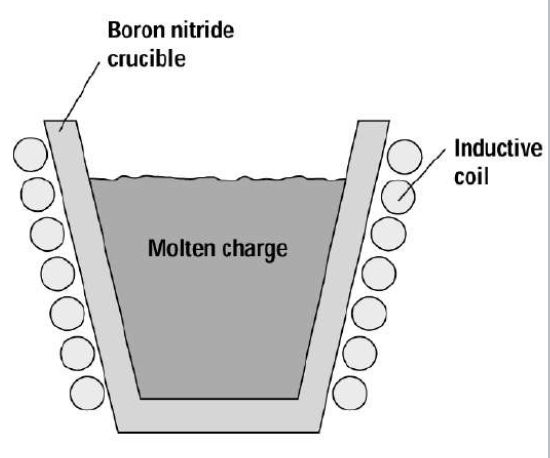
Inductive heating: inductive coil wound around crucible to evaporate charge. Courtesy of Columbia University
Thermal Evaporation
Thermal evaporation is one of the simplest forms of physical vapor deposition. In this process, a resistive heat source is used to evaporate a solid material in a vacuum environment to form a thin film. The material is heated in a high vacuum chamber until vapor pressure is produced. The importance of vapor pressure will be discussed more intensively in the next section. Subsequently, the evaporated material traverses the vacuum chamber with thermal energy and coats the substrate. As shown from the image below, the simplicity of this process makes it particularly popular when depositing metals with relatively low melting points.
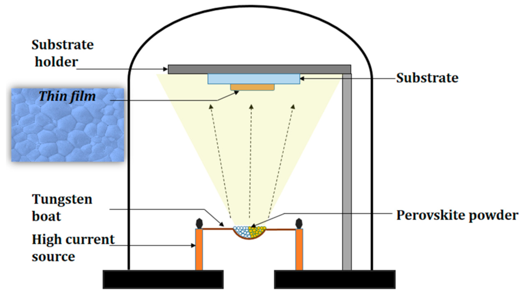
Thermal Evaporation: crucible heated by DC current through a resistive wire. Courtesy of Polymers Article by Saif M. H. Qaid et al.
Electron-beam Evaporation
Electron-beam evaporation uses a focused electron beam to heat and evaporate metals. The temperature of the electrons is typically around 3000 °C and a 100 kV DC voltage source accelerates them towards the target material. As mentioned prior, this process is very useful for depositing materials with higher melting points such as tungsten and tantalum. Evaporation occurs at a highly localized point near the beam bombardment site on the surface of the source. As a result, little to no contamination from the crucible occurs. Once the heated electrons strike the source material, they lose their energy very rapidly. The kinetic energy of the electrons is converted into thermal energy which heats up the source surface. Once temperatures are sufficiently high, vapor will be produced and coat the surface of the substrate. Some of the incident electron energy is lost through the production of X-rays and secondary electron emission.
Referring to the image below, the deflection plates placed before the bending magnet are used to raster scan the electron beam across the charge surface. Without raster scanning, the electron beam would melt through the crucible and eventually the vacuum chamber causing considerable damage.
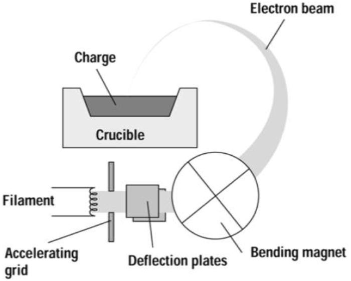
E-beam Evaporation: high energy electrons release the target atoms which travel outward in a vapor state. Courtesy of Columbia University
Considerations
Electron-beam evaporation requires the source material to be heated in a high vacuum chamber with a pressure of less than 10-5 Torr. A high vacuum is needed to minimize collisions of source atoms with the atoms of the background materials. For reasonable deposition rates, the vapor pressure must be approximately 10 mTorr. This makes it nearly impossible to evaporate some materials using thermal evaporation. Refractory metals must be evaporated using electron-beam evaporation instead. Referring to the vapor pressure curves below, evaporating platinum would require a temperature of about 2000 °C. This temperature is well beyond the operating range for thermal evaporation (~1800 °C). Meanwhile, electron-beam evaporation could easily handle temperatures that high.
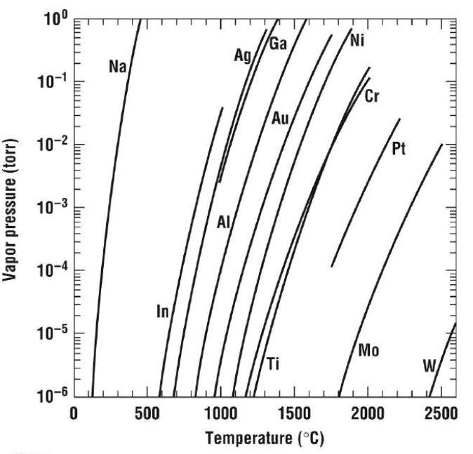
Vapor pressure curves for some commonly evaporated materials. Courtesy of Columbia University.
Because evaporation is an isotropic process, meaning atoms are evaporated off of the source in all directions equally, deposition uniformity becomes an issue. To combat this problem, manufacturers use spherical wafer holders like the one used below. The issue of deposition uniformity is not completely solved; however, since wafers directly above the crucible will be coated more heavily than wafers off to the side.
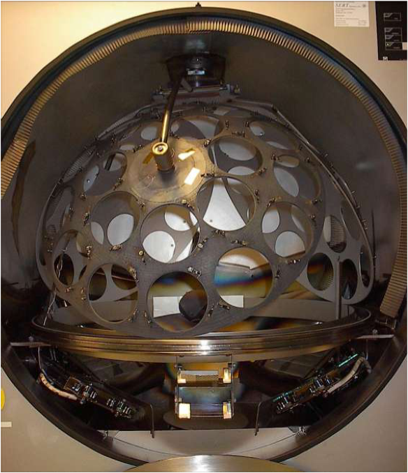
Spherical Wafer Holder: used to improve deposition uniformity. Courtesy of Columbia University.
Thermal vs. Electron-beam
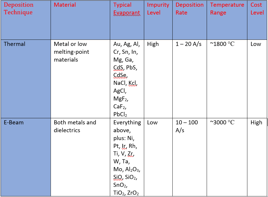
E-Beam vs Thermal Evaporation
Thermal evaporation is simple, robust, and commonly used. However, as shown in the table above, its evaporants are very limited and contamination from the crucible is very high. On the contrary, electron-beam evaporation is more complex, but extremely versatile. Virtually any material can be evaporated using this method and very little contamination is present.
