Goals of Engineering: Precision
In many cases, the goal of scientists and engineers is to affect some change in the world we live in via a rigorous understanding of the characteristics of some process or thing. Scientific interrogation provides a framework or lens through which one can cultivate an understanding of the world and its processes, and as the frontiers of science move forward, there is an ever increasing demand for higher and higher precision to be achieved. To this end, optics and optical engineering provide increasingly important tools to understand the world and its complexities. Within the realm of optics, diffraction gratings, and the phenomenon upon which their operation is based provide a useful tool to advance the frontiers of precision.
Why is Light Useful?
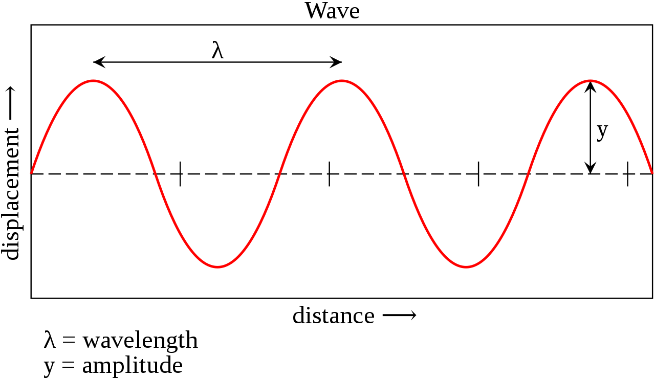
Light, whether from the sun, a candle, or a lightbulb, consists of periodic electromagnetic waves which propagate through space. The periodic nature of light means that at set intervals of space, referred to as a wavelength, the cycle of propagation starts over.

This image depicts a basic mathematical sine wave. As is demonstrated, the wavelength is defined as the length at which the cycle repeats itself, in this case, from peak to peak. Courtesy: Wikimedia Commons
The electromagnetic waves which comprise light range from 10^-16 meters (gamma radiation,) to 10^8 meters (radio waves.) For reference, check out this visual representation of the sizes of various objects in our universe.

A visual depiction of the range of the electromagnetic spectrum. Courtesy: Wikimedia Commons
The short end of the electromagnetic wavelength spectrum contains extremely small wavelengths. The manipulation of this regime of waves comprise some of the smallest and most precise measuring tools that can be utilized at this point in time.
However, it is not as simple as simply selecting a wavelength to use and finding the source that emits such a wavelength. In many cases, a source actually emits a range, or spectrum, of wavelengths. For example, the sun emits light which covers the entire visible spectrum and extends on either side into the infrared (longer wavelengths) and the ultraviolet (shorter wavelengths.)
For some applications, it is useful to distill a source’s emitted spectrum into its constituent wavelength components. An elementary example of this would be the filtering of a lightbulb’s emitted spectrum (white light, broad spectrum) into just its red component by utilizing a piece of red glass which only allows red light to transmit (the portion of the spectrum from roughly 630 nm to 700 nm,) and absorbs all other wavelengths in the emitted spectrum. Such an effect may be desirable for a light show at a concert.
For more technical applications, the desire to distill a wide spectrum into a narrower one is often still present, but the extent to which the spectrum needs to be distilled may be much higher. For many of these applications, an effective way of doing so is to incorporate a diffraction grating.
Single Slit Diffraction
Diffraction gratings exploit the phenomenon of diffraction to redirect light. Diffraction refers to the process by which light will bend around an edge or gap into discrete directions. The magnitude by which the light is bent is related to the size of the gap relative to the wavelength of light. The smaller the gap is with respect to the light, the larger the magnitude of the bending is.
The basic concept of diffraction for a single diffracted order is illustrated. Incoming planar light is incident on a slit of width W, and is diffracted at an angle θ. The magnitude of θ is related to W and λ, the wavelength of the incoming planar light. In reality, rather than bending into a single new angle, the plane of light will diffract into multiple angles at evenly spaced intervals, determined by integer orders. (m=…-1,0,1,2…) Courtesy: Wikimedia Commons
Diffraction gratings are also reliant upon the tendency of light waves to interfere with one another. Interference refers to the superposition of waves upon one another. There are two forms of interference: constructive and destructive.

This image depicts the phenomenon of constructive interference. As the two pulses of amplitude x overlap at t=1, their amplitudes interfere constructively to create a singular pulse of amplitude 2x. Courtesy: Wikimedia Commons

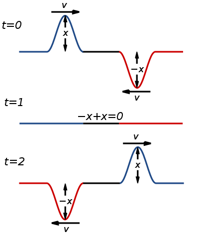
This image depicts the phenomenon of destructive interference. As the two pulses of amplitude x and -x overlap at t=1, their amplitudes interfere destructively to nullify each other’s amplitude. The result is a “pulse” or lack thereof, with amplitude zero. Courtesy: Wikimedia Commons
As mentioned earlier, when light is incident upon a narrow slit, it is diffracted not just into a single angle, but into multiple discrete pathways defined by discrete orders (m=-1,0,1,2…etc.) Because of this, a single beam of light, incident upon a single narrow slit is capable, and in practice will, interfere with itself as if there were multiple sources of light. This interference effect is directly related to the constructive and destructive interference diagram shown above.
In the case of electromagnetic waves propagating along in space, amplitude comes into play (as in the above diagram) as well as the phase relationship of various paths of light. the phase of light refers to it’s position within its periodically repeating pattern.
A tangible example of phase might be the minute hand of a clock. If one considers the face of the clock to contain 360 degrees (or 2*π radians), then the minute hand of the clock moves periodically through these degrees or radians every hour. The period, then, is one hour. At 15 minutes past the hour, the minute hand has moved 3/12, or 1/4 of it’s overall travel distance. It’s phase could be considered to be 1/4*(360), or 2*π*1/4⇒pi/2. At 30 minutes past the hour, it has moved 6/12, or 1/2 of it’s overall travel distance, the phase can be considered as 1/2*360, or 2*π*1/2⇒π, and so on and so forth. Until the cycle, and thus the phase, repeats itself at the top of the hour.
In similar fashion, a propagating electromagnetic wave has some phase component. As it travels, it periodically repeats its behavior. This phase component is critical to understanding the underlying source of the interference pattern observed via the diffraction grating.

This image depicts the physics at play when light is incident upon two narrow slits adjacent to one another. Each slit diffracts light independent of the other, but the diffracted light interferes. The alternating white and black bars on the right hand side of the image represent alternating areas of constructive (white) and destructive (black) interference. Courtesy: Wikimedia Commons
Resultant Intensity Pattern for Coherent Light
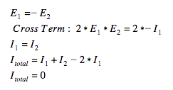
The quantity intensity is responsible for determining what we see. When someone refers to the sunlight being bright, or the light from a candle being dim, what they are referring to, from a technical standpoint, is the intensity of the light. The quantity of intensity is equivalent to the square of the incident electric field on a given surface. In the case of coherent diffracted light from two adjacent slits as we have discussed thus far, the electric field incident at a point is actually a sum of two electric fields. One from each of the adjacent slits. The resultant intensity is:![]()
We are most interested in the final term of this intensity relationship. This is referred to as the cross term. The cross term varies as the phase relationship between the two electric field varies periodically. When the two electric fields are in phase and sum constructively, the cross term is largest, and the overall intensity is maximized, resulting in one of the bright zones on the optical screen.

When the two electric fields are completely out of phase with one another and interfering destructively, the cross term is equal and opposite in magnitude to the remainder of the terms responsible for the total intensity. Thus, the overall intensity is 0, resulting in a dark patch.

In contrast to the case of coherent light, incoherent sources, or those in which the light has no definite phase relation between the two incident fields, yield a much less interesting pattern. The lack of phase relation means that the cross term does not come into play, and instead, we are just left with the sum of intensities of the individual fields. For a more rigorous mathematical analysis check out section 14.3 of MIT’s course notes on interference and diffraction.
Finally, it is also important to note that if multiple wavelengths of light are incident upon the diffraction grating, they will diffract into discrete angles. This makes diffraction gratings a useful tool for isolating a single narrow band of wavelengths, as one can orient a grating such that only the desired gratings stay within the relevant optical path. Other wavelengths will travel along other directions, and can be discarded or ignored in this way.
This article is the first in a series and begins to cover the fundamentals of the diffraction process. See the next article here to read more on the underlying science behind these tools as well the history and areas of application for this phenomenon.
