Testing the quality of optical surfaces can reveal defects and imperfections in optical surfaces. These imperfections can induce aberrations in optical systems. Consequently, identifying to what extent the quality of an optical surface alone can have on the system performance can be useful. It turns out, there are both interferometric and non-interferometric methods for testing optical surface quality, as we will explore in this blog post.
Today's post is sponsored by Gentec-EO - a leader in laser beam measurements.
Non-Interferometric Testing
Spherometer
These instruments can be used to measure the radius of curvature of a spherical surface. A spherometer has three legs that rest on an optical surface. In the center, there is another point, or leg, that is translated up or down using a micrometer. The displacement of the screw effectively measures the curvature of the surface at that location. Therefore, from the measured curvature, it can be determined if the surface meets the correct specifications. Spherometers may either come with a flat surface as a reference to zero the instrument, or may require an optical flat purchased separately to calibrate.

The spherometer is supported by three legs and then adjusted until the center screw meets the curvature of the surface. Courtesy of Eisco.
Shack-Hartmann
To set up a Shack-Hartmann test, an image sensor is placed at the focus of a focal plane array. This can also be done with an array of pinholes instead of lenses. The position of each of the points imaged from either the focal plane array or the points focused from the pinholes are calculated using the sensor. The positions of the points, if deviated from the perfect grid expected by the array, can reveal the wavefront error induced by the optical component being tested.
Basic Methods of Interferometric Testing
For interferometric testing, there are two main methods of creating interfering beams of light. These are division of amplitude and division of wavefront. The former involves dividing an incident beam, propagating them along different paths, and then recombining them to cause interference. The latter uses a coherent point source (or a coherent slit source) and divides the wavefront using components like prisms or side by side apertures.
Division of Amplitude
Fizeau Interferometer
Fizeau interferometers can also be used to determine the quality of optical surfaces. In a Fizeau interferometer, a reference beam is sent into a beam splitter. One path of the split light is not used (or dumped). The other path is directed through a reference surface followed by a test surface and is then reflected through those elements using a mirror. The reference surface is usually a high quality optical flat. The mirror should also be of high quality.
The reflected light from the elements is then directed back through the beam splitter and is collected and imaged onto a sensor. The interfering fringes imaged by the sensor can be analyzed to determine if there is any wavefront error. This fringe pattern is a result of the difference in phase between the reference surface and the test surface. Since the reference surfaces are high quality, the only deviations in the output should be from the test surface if it is imperfect.
Twyman-Green Interferometer
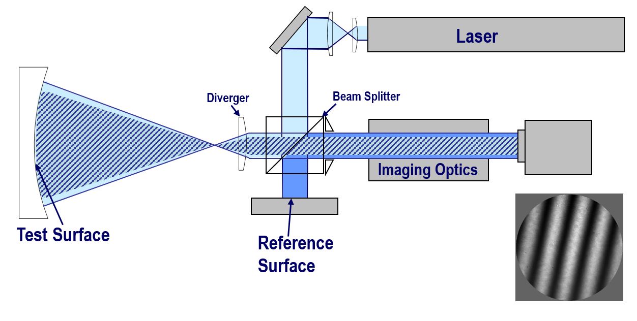
The Twyman-Green interferometer uses a collimated point source. This input is sent through a beam expander where it then hits a beam splitter. Instead of one arm of the beam splitter light being dumped, it is directed to a reference mirror and then sent back through the beam splitter. The other arm directs the light either to a test mirror which reflects the light back through the beam splitter, or the light passes through a test lens and is then reflected by a reference mirror back through the beam splitter. After the two paths recombine and interfere at the beam splitter, they can be imaged and detected with a sensor. Again, the resulting fringe pattern can reveal the aberrations present in the system due to the test optic.

Twyman-Green interferometer setup with example interferogram (bottom right). Courtesy of 4D Technology
Division of Wavefront
Shear Plate Interferometer
The shear plate is one of the simplest interferometers. They are commonly used to check the collimation of a lens in a system. Shear plates are virtually a plane parallel plate oriented at a 45-degree angle to the incoming wavefront. The plate creates two reflections of the incoming beam which interfere. The interference creates bright fringes where there is constructive interference and dark fringes where there is destructive interference.
Wedged shear plates also exist, where the plates are not parallel, but angled (or wedged) with respect to each other. It is easier to determine the beam condition using a wedged shear plate. On the wedged shear plate output, there is usually a reference line. The fringes rotate about this reference line depending on whether the light is converging or diverging. When the fringes are aligned with the reference line, then the incoming light is collimated. If there are aberrations, the shear plate output will deviate from perfectly straight lines. Based on the fringe output, it is possible to analyze the interferogram and determine the wavefront error, and thus, the aberrations in the system.
Lloyd’s Mirror
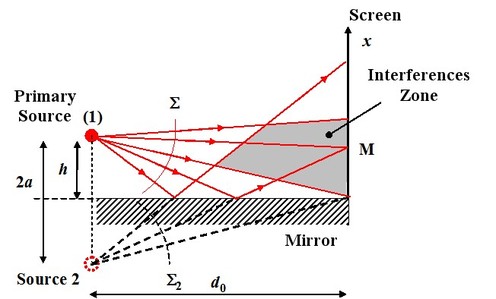
This setup builds of off Young’s double slit experiment. A primary source is positioned above a mirror. The mirror is perpendicular to the plane of the viewing screen. The reflection of the source off the mirror creates a virtual point source. Now the system acts as if there are two sources instead of one. The wavefronts from each of the sources interfere and create an interference pattern on the viewing screen. A Lloyd’s Mirror setup is sometimes used to inspect planar surfaces.

Diagram depicting how a Lloyd Mirror device works. Courtesy of Optique.
These are by no means the only methods for testing optical surface quality, nor are they all the different types of interferometric and non-interferometric testing. There are many different variations of these types of testing. Some even include built-in software that calculates the wavefront error and will correct for surfaces that are not completely aligned with the beam path. Do you know any other methods for testing optical surfaces? Please leave in the comments section below.
