Most are used to seeing lenses with very set radii of curvature. Typical lenses have surfaces that are plano, convex, concave, or any combination of those. Even in the cases of aspherical lenses or cylindric lenses, there are still fairly straightforward and established ways to describe those types of surfaces. But what about freeform optics? Designs for anamorphic optics include any mixture of spherical, aspherical, and toroidal surfaces. Freeform optical elements are not constrained to these parameters. They do not exhibit the rotational or translational symmetry which are found in standard optical components. Freeform optics can include both lenses and mirrors. The asymmetry that these freeform elements possess provides more degrees of freedom than a symmetrical element.
.webp)
Examples of some freeform optics shapes. Courtesy of DynaOptics.
Today’s post is sponsored by Connet Laser Technology – a leader in the design and manufacture of fiber lasers and amplifiers
Benefits of Freeform Optics
Just like other optical systems, freeform optics can be designed to compensate for aberrations. Unlike other optical systems, however, the higher degrees of freedom can be utilized to better correct for aberrations than symmetrical elements, including simultaneous correction of different aberrations. As a result, systems with freeform optics tend to possess a higher field of view and a larger numerical aperture. Deeper depths of field can be achieved using freeform elements, too. There are many cases where using freeform optics also minimizes the size of a system when compared to using rotationally symmetric elements. It can improve the functionality of each element. Thus, freeform optics can reduce the number of optical surfaces required in a system. This reduces the overall dimensions of a system and decreases the complexity of the system’s assembly.
Freeform Applications
Freeform optics serve a variety of systems. Heads up displays (HUDs) and head mounted displays (HMDs) are two areas where freeform optics are very useful. Freeform elements have made it possible to create more compact HUD systems and optimize performance despite the pupil location. Other areas of application include sensors in the automotive industry in driver assistance systems. Some imaging systems use freeform optics, as do some illumination systems.New
Freeform optics have been used in numerous LED systems. They have been designed to control the intensity distribution and pattern of the emitted light more accurately, as well as increase efficiency. The angular color uniformity has also been improved in white LEDs for a more uniform illumination over a wider range of angles.

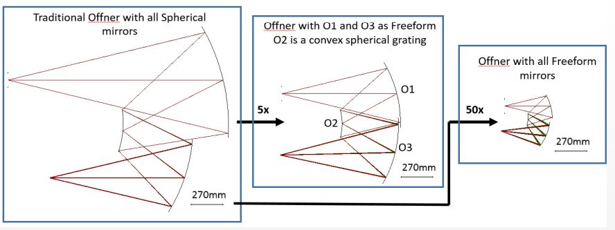
Graphic showing the differences between the Offner Spectrometer configurations using traditional mirrors and freeform mirrors. Courtesy of NASA.
In some instances, freeform elements have replaced mirrors used for folding a beam path. For example, NASA summarized the effects of using freeform optics in their roadmap for their next decade. One proposal featured replacing traditional mirrors in an Offner Spectrometer design with freeform mirrors. They reported that the volume of the Offner spectrometer design could be reduced by a factor of five using two freeform mirrors. Even more impressive, NASA reported that by using all freeform mirrors the volume of the Offner spectrometer design could be reduced by a factor of 50 while retaining the same field of view. The freeform surfaces would also compensate better for incident light coming in at steep ray angles. Both aberration correction and volume of the design were optimized with the simulated freeform configuration. Freeform optics do have clear advantages, but it can be a challenge to characterize a freeform lens or mirror.
Design of Freeform Optics
One of the more common methods of optical design for freeform optics is called direct mapping. Direct mapping correlates the distribution of light from the source to the ideal light distribution at the target. From these distributions, the ideal surface points for the freeform optic can be backed out of the data by fitting it or interpolating it. There are a few different methods of direct mapping, but have been proven to produce accurate characterizations of high quality lenses.
Fabrication Methods
The fabrication methods for freeform elements are generally the same as those for creating rotationally invariant elements.
There is a Zernike polynomial function that can help describe the deviation in wavefront error using a freeform surface. This is an important metric to quantify the quality of the lens, especially since it is very commonly used with respect to rotationally symmetric optical elements. Since it is such a common metric, many manufacturing and testing software use Zernike polynomials to describe surfaces accurately mathematically. This makes it easy to characterize freeform surfaces using existing programs, though it may take longer and require more data.
Machining Freeform Elements
Grinding (or milling) and polishing lenses to freeform shapes is one of the many fabrication methods. This can be achieved using diamond cutting or nano cutting for precise shaping. Usually, slow slide servos or fast tool servos are used for diamond turning in lens fabrication.
Injection Molding
Recent developments in freeform optics have made it possible to produce lenses by using a liquid polymer. Injection molding allows one to quickly manufacture large quantities of lenses. Injection molding is already used for optical elements that are rotationally symmetric about the optical axis. It becomes trickier, however, in freeform systems, as all six degrees of freedom must be more carefully considered.
To create well-constructed lenses using injection molding, the first step is to create an accurate mold. Molds are generally described in software and tooled using a CNC machine. A profilometer can be used to measure the accuracy of the mold surface. Once the mold is of satisfactory quality, the material being used may be injected. As with all optical designs, when selecting a material, it is important to consider material qualities and properties and how they may change depending on the wavelength of the incident light.
