If you need to control the state of polarization of your light or change the direction of polarization of your beam or change from linear polarization to circular polarization (or vice versa) or create any other specific state of polarization then you will have to use waveplates. The purpose of a waveplate is to introduce a specific phase difference or retardation between the two orthogonal components of the electromagnetic light. When the plate introduces a retardation of 90°, then the plate is called a quarter wave plate, for a retardation of 180° it is called a half wave plate. Normally, a waveplate will introduce a particular retardation only for one specific wavelength and for one specific orientation of the plate with respect to the direction of light propagation; also the temperature has an influence on the actual retardation. Waveplates are available in various materials, and they come in three basic types:
1. Multiple order:
These create a large phase difference, several times the wavelength plus a fraction of the wavelength, but only the fraction is effective because multiples of 2π cancel out.
2. Quasi zero order:
These consist of a pair of almost identical multiple order plates with crystal axes oriented orthogonally, such that only the difference in phase retardation is effective.
3. True zero order:
These are extremely thin, such that they create a phase difference which is truly only a fraction of a wavelength.
Before selecting the material, the appropriate type should be determined. If your light beam
1. is directionally stable,
2. is well collimated,
3. has narrow spectral bandwidth,
4. travels in a thermally stable environment,
5. has low intensity, both spatially and temporally,
then the type does not really matter, and you should make your selection mainly based on price and other optical properties which are important for all kinds of optical components (apart from other considerations such as lead time, reliability etc. which you apply in all purchasing decisions). If any of the above conditions is not fulfilled, then the decision about the appropriate type will be more demanding. In the following analysis, the impact of the above conditions on the performance of the three types of wave plates is examined. Retardation precision is shown for the following examples which are paradigmatic for commercially available waveplates:
1. Multiple order plate: single Quartz plate, approx. 1mm thickness,
2. Quasi zero order plate: compound Quartz plate (cemented, optically contacted, or air spaced), approx. 2mm total material thickness (excluding air space),
3. True zero order plate: Mica or Polymer, bare or cemented between glass flats, thickness corresponding to true zero order condition. Wavelength of light is in the green range (around 500 nm), and all waveplates are considered to have a good antireflective coating. Let us first consider the influence of direction of light on phase retardation. When the plate is rotated around an axis parallel to the crystal optical axis, then the phase retardation increases approximately with the square of the
angle of rotation, whereas for rotation around a perpendicular axis it decreases. The absolute values of increase and decrease for identical rotation angles are not exactly
the same, but almost indistinguishable for all practical cases. (Please note that “increase” and “decrease” do not have an absolute meaning here but relate to the phase retardation at zero rotation: If this phase retardation is negative, then “increase” means that it becomes even more negative.)
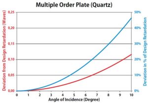
The following three diagrams show the deviation from design retardation for the three basic types of waveplates, both as absolute deviation (left scale, red line) and
as a percentage of design retardation (right scale, blue line). The results are independent of the particular design 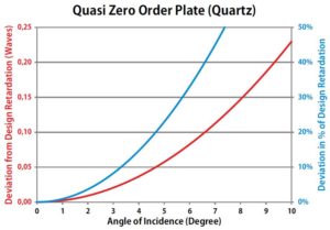 of the waveplate, i.e. it does not matter if the plate is a quarter wave or a half wave plate or any other retardation value: the deviation is always the same. Please note that the scale for absolute deviation for true zero order plates differs (is decreased by a factor of 100) from the corresponding scale for the other two types so that the deviation becomes visible. What can be
 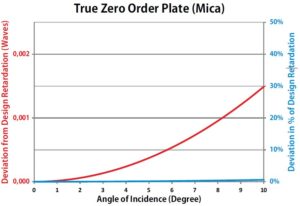 learned from these diagrams?
• Waveplate which are not true zero order plates have a strong dependence of retardation on angle of incidence.
• Quasi zero order plates even produce twice the error produced by multiple order plates. Actually, at 10° angle of incidence a quarter wave plate almost becomes a half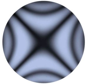 wave plate and vice versa.
• The dependence of retardation on angle of incidence is almost invisible for true zero order plates and practically negligible for most real life applications. This means that true zero order plates should be used whenever the relative orientation of the light beam with respect to the waveplate is not fully controlled. But this is not just a matter of mechanical instability or similar effects, but also a matter of beam collimation.
When the beam is not perfectly collimated, then it contains a variety of ray directions ‒ within the cone of beam divergence. All these ray directions will have different angles of incidence on the wave plate, resulting in different phase retardation for different ray directions. Therefore an initially completely polarized divergent light beam will become partially depolarized on transmission through a waveplate. Evidently, the depolarization is not uniform over the angular field, but varies with the individual direction of each light ray. As mentioned above, retardation is decreased for rays which form an angle ≠90° with respect to the crystal optical axis, whereas it is increased for rays which are tilted in the orthogonal plane, with the interesting side effect that retardation is not changed for beams which are tilted by the same angle in both planes. All this results in an intensity pattern similar to the pattern shown here when a divergent, initially linearly polarized light beam is transmitted through a multiple or quasi zero order half wave plate and then through a linear polarizer.
The retardation of any given wave plate also depends on temperature for two reasons:
• The plate thickness varies with temperature.
• The indices of refraction, and consequently the birefringence, depend on temperature.
These effects vary with material, but for Quartz and Mica the temperature dependence is similar. For any given material the following statement is correct: Quasi and true zero order plates exhibit much less temperature dependence than multiple order plates made of the same material. As an example for quarter wave plates made of Quartz: The multiple order plate will be approximately 80 times more sensitive than the quasi zero
order plate.
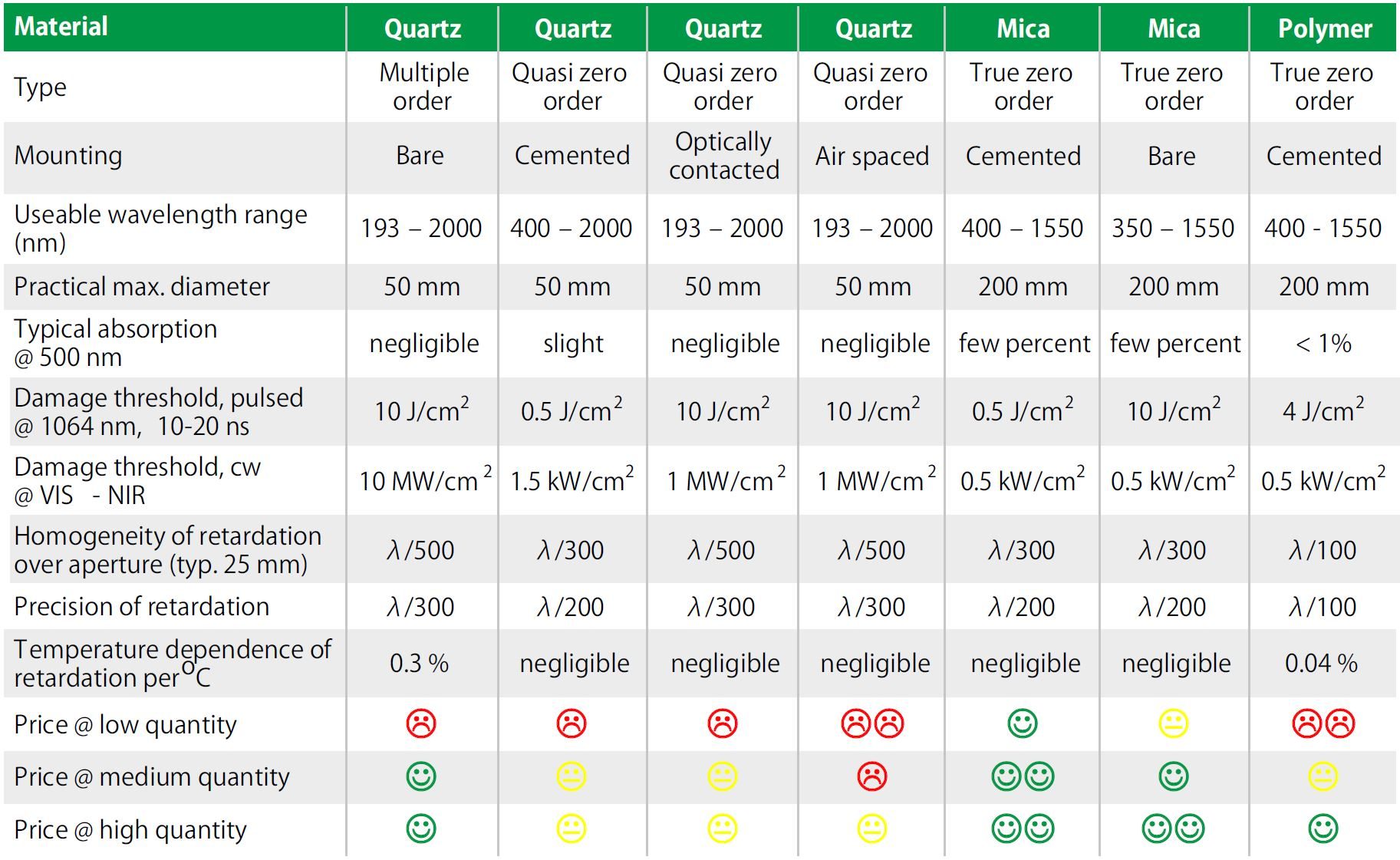
In the following table, the main combinations of technology and optical material are compared from a practical perspective as far as they differ significantly. Bare Polymer retarders are not included in this table because ‒ due to their extremely small thickness ‒ they are highly fragile and not suitable for the vast majority of applications:
The table clearly demonstrates the advantages as well as the disadvantages of the various types of waveplates. A clear advantage of Quartz is the usability in the UV and the very high damage threshold, especially the continuous wave damage threshold which results from the very low absorption of Quartz. Otherwise, Quartz is
usually not the material of first choice, particularly due to the pricing which can be prohibitive unless a multiple order plate can really be used in the application.
The absorption, and the associated lower cw damage threshold, of Polymer and Mica are essentially the only disadvantages of these materials in relation to Quartz.
Therefore, usage of these materials is generally advisable unless the particular application clearly calls for one of the positive features of Quartz. And unless the lower
absorption in Polymers justifies a considerably higher price, true zero order plates made of Mica are the best choice for a vast majority of applications, especially when price is a consideration. For Mica, “low price” generally even coincides with “good availability”: Well established producers of Mica retarders, such as S & R Optic GmbH, usually have a great variety of bare Mica sheets in single nanometer gradation available on stock, so that waveplates for almost any wavelength in the usable range can be made by just assembling an already existing Mica sheet.
In conclusion:
• True zero order plates are the best choice under technical considerations.
• Quasi zero order plates behave well regarding wavelength and temperature effects, but behave even worse than multiple order plates otherwise under variations of beam direction.
• Multiple order plates are only useful when all optical parameters are well controlled.
• Cemented Polymer retarders are a good choice technically, but are usually very expensive.
• Mica retarders are generally the preferred choice from a technical point of view, and typically they are more easily available and come at a lower price.
For more details, visit S&R Optic GmbH or go to the product listing pages on FindLight.
The original version of this article has been written by Dr. Wolfgang Schneider and can be found on the website of S&R Optic GmbH. FindLight has a permission from Dr. Schneider to post the abridged version of the original article in the FIndLight Blog to make it available to a wider audience.
About S&R Optic GmbH
 S & R Optic is a global leader in the design and production of advanced, high quality crystal optical components for demanding applications requiring high performance and durability. Through constant interaction with our customers and understanding their needs, S & R Optics guarantees our performance specifications, high quality and consistent reliability for both our standard and custom designed optical components.

