It turns out Fiber Bragg Gratings have a noteworthy application in aerospace industry that we will explore today together. Because of their phenomenal optical multiplexing capabilities they can act as smart sensors that help monitor the structural integrity of airborne vehicles and allow to maintain and lengthen their lifetime. This is a very important application in spacecraft industry where errors and damage can mean a matter of life or death for the crew aboard.
In today’s blog post we will learn about Fiber Bragg Gratings and their use as acousto-ultrasonic sensors in spacecrafts – an exciting industry that has taken a new breath by the emergence of such rising stars as SpaceX, Orbital Sciences, Sierra Nevada Corporation, Virgin Galactic, XCOR Aerospace and others givings us the promise of one day taking a vacation trip to the moon.
What is a Fiber Bragg Grating?
A Fiber Bragg Grating is a thin, tubular device (just like an optical fiber) that contains a physical “grating” area at its core.

Diagram of an optical fiber, showing core and surrounding cladding.
Courtesy of RP Photonics Encyclopedia
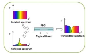
In Fiber Bragg Gratings, the fiber core is not homogeneous but rather has a periodic variation in the refractive index of the material. The said periodicity is usually on the order of hundreds of nanometers, except for long-period FBGs. Because there is a change in the refractive index of the core, some light will be reflected and some will be transmitted through the tube. The wavelength of light that is reflected vs transmitted is dependent on the periodic spacing of the grating. For instance, if the light wavelength satisfies the Bragg condition (wavelength is about half the periodic spacing between gratings), it will be reflected.
It is easy to see that FBGs effectively act as narrow bandwidth filters of light. It can be used to block certain wavelengths and transmit others, a bit similar to the mode selection that happens in laser cavities.

Diagram showing how FBGs work.
Courtesy of FBGS.com
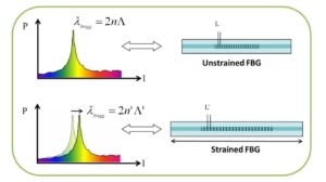
The properties of FBGs and the wavelengths they reflect can be influenced by pressure and strain that may stretch or compress the grating period. Additionally, temperature may also cause thermo-optic effects in the Silica/ doped Silica material that FBGs are usually constructed from. Some other factors that would affect the grating include vibration and displacement. All these sensitivity to external stimuli enable the utilization FBGs as sensors to measure many different physical effects at the same time. This is an important fact that engineers have exploited in sensing and monitoring applications for Aerospace and Spacecraft industries as we will soon see.

Effect of strain on an FBG. Reflected and transmitted wavelengths are shifted with change in period.
Courtesy of FBGS.com
The Horace Lamb Waves
FBGs can be used to detect ultrasonic and acoustic wave signals, with a unique application in structural health monitoring of aerospace vehicles. One important type of ultrasonic signal to detect is so-called Lamb wave. Lamb waves are elastic waves, discovered by an English mathematician Horace Lamb in 1917. Although purely a mathematical concept at the time, it had a very interesting property such that the particle motion in these waves lie in the plane that contains the direction of wave propagation and the plane normal. As a corollary, these waves are capable of propagation of rather large surface areas without significant deterioration in the form function. In a spacecraft this is especially handy as it is often sectioned off into plate-like structures, and Lamb waves are one of the furthest traveling signals that propagate into those plates.
One method to detect Lamb ways is by using Fiber Bragg Gratings in acousto-ultrasonic detection.
Fiber Bragg Grating Applications in Structural Health Monitoring
Acousto-ultrasonic detection is used for damage detection when the spacecraft is on the ground (not mobile). To generate the ultrasonic signals an ultrasonic actuator is needed. This form of damage detection is very precise and quantitative, as the form function of the waves and the repetition of measurements can both be controlled. However, the resolution and the bandwidth limitation of traditional instruments used with FBGs, like optical spectrum analyzers, don’t allow for precision in high frequency detection.
For precise detection of ultrasonic waves, we must use a demodulation technique to interpret the detected signals. There are four demodulation techniques in practice and in laboratory testing: broadband light source (power detection), laser light source (edge-filter detection), Erbium-Doped Fiber Laser (EDFL), and modulated lasers. Another important factor in ultrasonic detection is the installation method of the Fiber Bragg Grating.
To incorporate the FBGs into a vehicle or craft, engineers use a few different methods. Some work has been done to place them into composite materials, such as inside of a fiber honeycomb sandwiches. [1] But this method may induce signal distortion, so a better method for spacecraft can be found by gluing FBGs on with some adhesive, such as epoxy. The particular choice of adhesive and a fiber coating is important to the strain sensitivity of the FBG.
Ultrasonic Signal Detection Experiment
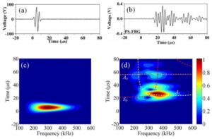
Results of a typical experiment with FBG and Carbon Fiber Reinforced Polymer (CFRP) are illustrated in the figure below. A FBG is placed 70 mm away from an MFC (flexible actuator) that could generate a 150 V peak-to-peak voltage signal, all glued on top of a small quasi isotropic CFRP. If there is damage to the plate, the Lamb wave will be different from its input signal. For example, in laminated specimens damage may mean that the plate thickness may vary and affects the detected signal.
To study and decipher the exact damage information contained in this detected signal, we can compare the amplitude attenuation and mode changes of the different signals. For instance, analysis of the A0, A1 modes (0th and 1st order Anti-symmetric) and S0 modes (0th order Symmetric) of the detected signal is needed. These modes can be found through comparing the theoretical curves of the group velocities of the laminate with the detected wave signal. Work has been done using the time delays of the two signals to find the size and process of debonding in areas on CFRP double-lap coupons. [3]

(a) input signals; (b) detected signals; (c,d) corresponding wavelet transform results
Courtesy of Wu et al.
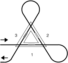
Further work has been done by Betz et al. to create a “FBG rosette” structure with three Fiber Bragg Gratings in a triangle shape. By collecting three signals in three different locations, we can more accurately decipher locations of damage in larger craft. Their experiment resulted in finding their detection locations to be very close to the damage locations. [2]

A FBG rosette diagram with signal flow and communication illustrated by black line.
Courtesy of Ferdinand et al.
—
Further reading on this topic
[1] https://www.sciencedirect.com/science/article/pii/S1877705812026185
[2] https://journals.sagepub.com/doi/abs/10.1177/1475921707081974
[3] https://www.sciencedirect.com/science/article/abs/pii/S0266353805002782
Did you know, FindLight has a vast collection of products using Fiber Bragg Gratings. Check out the catalog of Fiber Bragg Gratings for sensors , lasers, and Phase shifted FBGS.

This blog is perfectly elaborated and explained. Structural Health monitoring is necessary to do.