Plasma Arc Cutting, commonly referred to as PAC is a manufacturing process that is associated with a range of electrically conductive materials such as stainless steel, manganese steel, titanium alloys, copper alloys, magnesium alloys, and cast iron. The concept of plasma cutting was developed as a byproduct of plasma welding in the 1960s but became a more productive method for cutting by the 1980s and 1990s . It was introduced as a solution for cutting electrically conductive materials that could not be cut by the more conventional methods such as mechanical cutting or laser cutting.

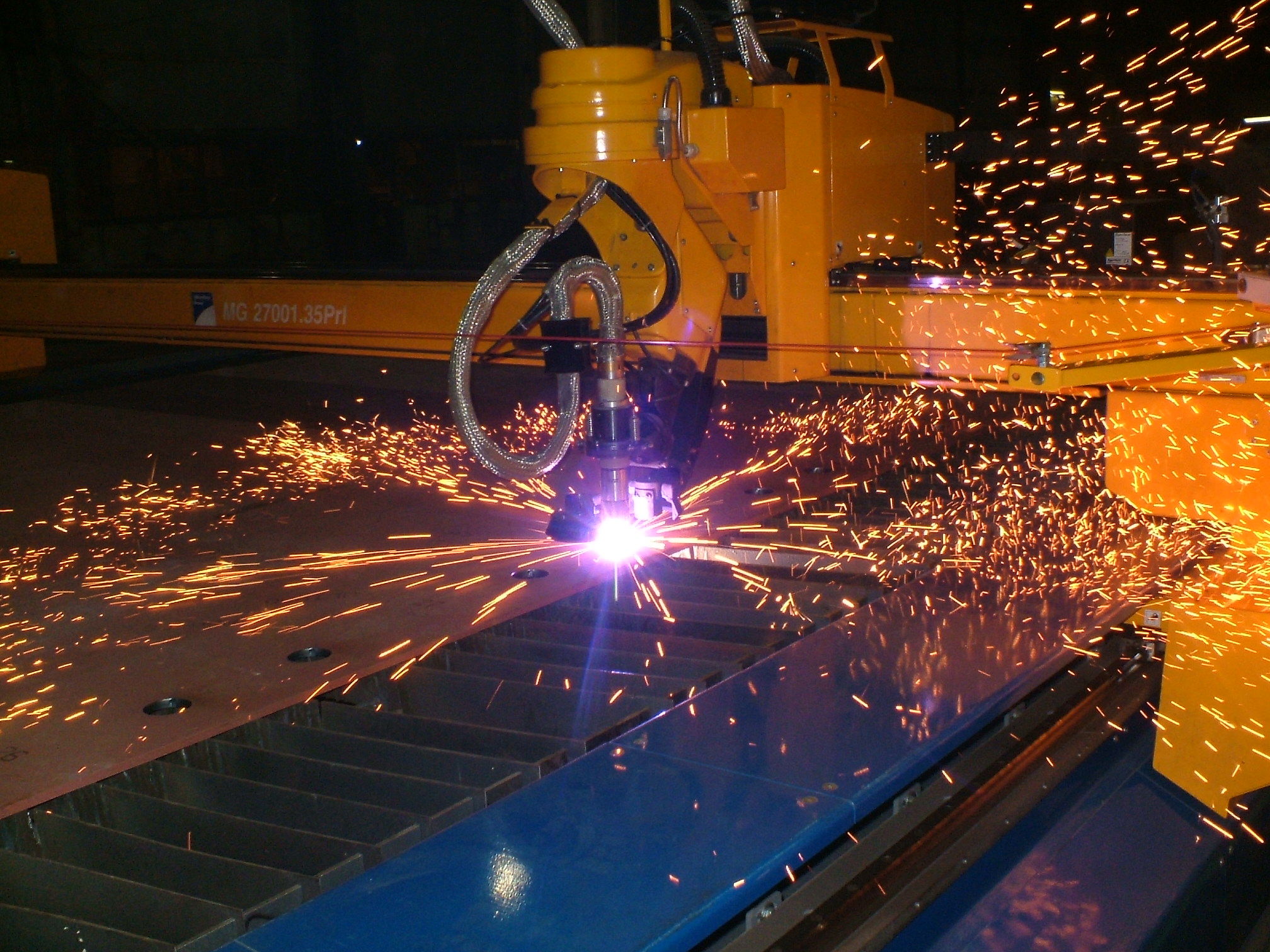
CNC Plasma Cutting (Source : Wikipedia)
The Plasma arc cutting method utilizes a superheated ionized gas through a plasma torch to cut through electrically conductive materials. Using this method, one can easily cut through electrically conductive materials within the range of 0.5mm to 180mm. Plasma cutting process is characterized by the presence of an electric arc between a cathode and the work piece material which acts as the anode.
Detailed Processes Behind Plasma Cutting
The entire plasma cutting process happens over several distinct phases starting from the pilot arc generation and finishing with the movement of the plasma arc over the object being cut.
1. Pilot Arc Generation
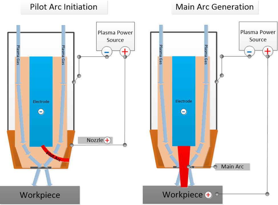
The setup in this process looks like the one shown in the figure below. The first step is to give a command that enables the power supply to generate up to 400V of no-load voltage, which is basically the voltage at the terminal when zero current is drawn from the power supply. The power source also applies a negative voltage on the electrode establishing it as the cathode and a temporary positive voltage on the nozzle, establishing it as the anode. Note that the nozzle will only remain as the cathode for this phase of the process.
Then a high-frequency, high-voltage potential is generated between the nozzle and the cathode, which then gives rise to a high frequency spark. The spark is responsible for ionizing the plasma gas which gives rise to low resistance current between the cathode and the nozzle.

Comparison of Pilot Arc Generation against the Main Arc Generation. Photo Courtesy of ThomasNet
It is important to note that the high frequency spark method has a lot of disadvantages, for instance, it can interfere with sensitive equipment, and can cause potential electrocutions, machine, and spark gap maintenance. Hence, alternatives have been developed such as capacitive into a primary circuit using a silicon-controlled rectifier. This method releases shot burst of energy which in turn creates a spark, which can be utilized for the arc. Another method is using a spring-loaded design in the plasma torch head. This method is also more popular than the high frequency method discussed earlier for its operational safety benefits.
2. Primary Arc Generation
The next phase after the pilot arc generation is the main arc generation where the pilot arc is pushed through the nozzle along with the plasma gas. The gas flow forces the pilot arc to come in contact with the grounded, electrically conductive workpiece. The plasma arc then transfers over to the workpiece, forming the main arc, which is responsible for generating and sustaining the plasma that is used in the actual cutting process. This in turn establishes the main-arc circuit which introduces the workpiece as the new anode as mentioned previously. Moreover, the arc transfer also forces the power source to reopen the open nozzle contacts to remove the nozzle from the pilot arc circuit and the main arc which in turn optimizes the cutting current.
3. Localized Heating and Energy Transfer
This phase is then followed by the localized heat transfer to the object being cut. At this stage the nozzle constricts the ionized gas flow and directs the main arc. The plasma produced in this fashion is nearly 20,000°C hot and is released at ultrasonic speeds. The combined high thermal and acoustic energy are responsible for the precise cutting of the electrically conductive materials. If you were to look at the plasma cutting at a microscopic scale, the process would be of localized heating, melting and vaporization exactly in that order.
The high thermal energy coming from the plasma is absorbed by the surface of the workpiece. This localized but massive energy absorption leads to weakening of the bonds among the atoms of the metals which leads to melting and vaporizing. The portion of the material that was removed to make the desired cuts is expelled out of the kerf, which is essentially the width of the cut that is created on the workpiece material. This phase is also referred to as the material ejection phase.
4. Moving the Plasma Arc and CNC Control
The next and the final phase is the arc movement, which is basically moving the plasma arc across the surface of the workpiece either manually or automatically to produce long consistent cuts. The movement must be unfaltering and uniform to produce cuts that are accurate to the required design measurements. This is often accomplished using a CNC (computer numerical controlled) machine that enables precise control over one ore more axes. Many Plasma Cutting Systems come equipped with CNC capabilities. This enables cutting with higher precision when compared with cutting by handheld equipment.
Advantages and Disadvantages of Plasma Cutting
Plasma cutting is an important alternative for cutting electrically conductive objects that require significant precision. It offers relatively simple technology that is easy to learn and operate. They are also cost effective compared with Laser Cutters with simple handheld units costing as little as a few hundred dollars. Many Plasma Cutting Systems come with integrated CNC capabilities that offer generous flatbed working space to cut large sheets of metal.
However, Plasma Cutting also has some disadvantages that one might be aware of before adopting the technology. Despite its relative affordability, plasma cutters are not able to provide the level of precision and control that some other cutting methods (e.g. laser cutting) offer. Plasma cutting is also limited in the thickness of the material with 200mm being the high end of the thickness that it can cut. They are also characterized by relative large kerfs that might not be suitable for some applications. Their working principle limits their use to conductive materials, so that if you need a more versatile tool, plasma cutting might not be the best option. Finally, plasma cutters do require some maintenance with a few components such as the nozzle and the electrode considered as consumables.
Let’s look at a few alternatives to plasma cutting and see how they compare.
Plasma Cutting vs. Laser Cutting
Plasma cutting may be a great cutting method, but it has its disadvantages. It’s not suitable for materials that can be easily melted and vaporized as you would end up with unfavorable cuts. In terms of precision, it is also not the best as it essentially melts and rejects part of the material away. It is also not suitable for every manufacturing process and that is why alternatives may be sometimes required. For instance, laser cutting is a method where a laser beam is utilized to make desirable cuts on materials ranging from metals, plastic, wood, glass, and ceramics. Laser cutting method uses laser beam concentration which produces very precise cuts and high-quality edges. It also requires lower level of maintenance and has a higher degree of operational safety.
However, it’s not the best choice when it comes to things like reflective materials. For such materials, plasma cutting can be a great alternative. It is also, generally speaking, cheaper to start with compared with laser cutters. For thick metal sheets and heavy duty workloads, plasma cutters can outperform laser cutters in terms of operational costs and throughput.
Plasma Cutting vs. Mechanical Cutting
Now comparing plasma cutting to the most common form of cutting; mechanical cutting. This method is a more contact-based process involving sheer mechanical power to cut through material using powerful equipment such as drill press, lathe, milling machine and so on. The method is more abrasive and does not possess the fine touch that is observed in plasma cutting. However, mechanical cutting is still used quite popularly as it has a wider range of applications and can cut through tougher things as compared to both plasma and laser cutting.
In summary, plasma laser cutting is an excellent and relatively low cost alternative for cutting electrically conductive materials. It is particularly well suited for cutting sheets of metal up to 200mm in thickness which require smooth edges but are not particularly concerned with the kerf size. Plasma cutters offer relatively simple and mature technology that is easy to learn and operate. They do come with maintenance requirements but these are pretty routine and can lengthen the lifespan of the machine. Many plasma cutters are equipped with CNC capabilities allowing to perform automated and controlled cuts.
If you liked this article, please subscribe and share. Also, comment below for ideas and suggestions.


