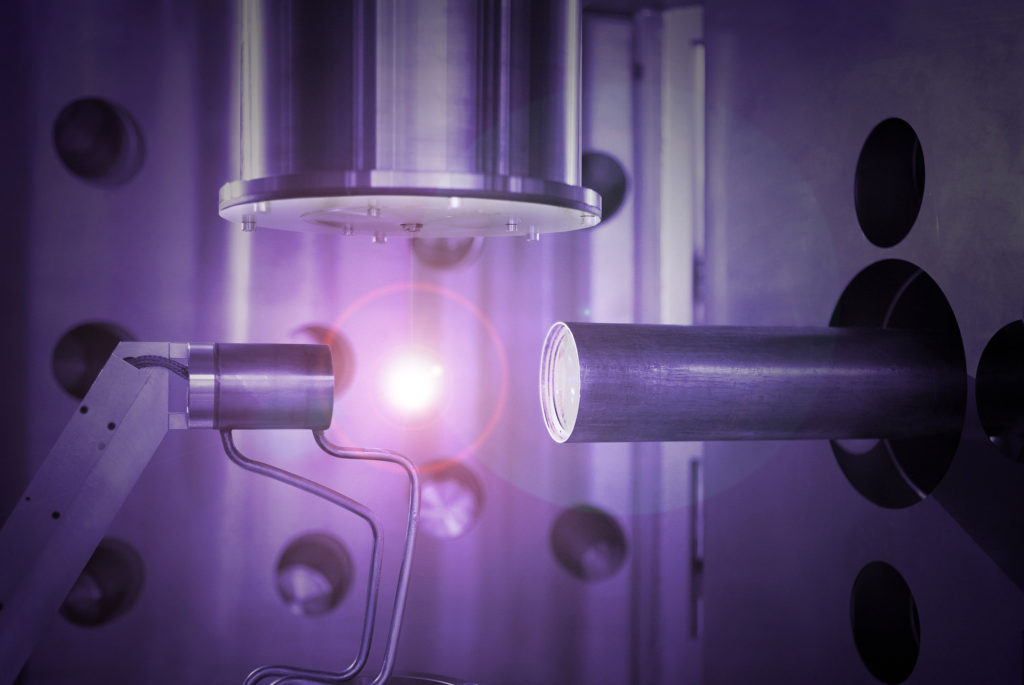
Laser-produced plasma light sources are especially powerful, precise, and controllable. Courtesy of Adlyte Inc.
Introduction to Plasma Light Sources
Moore’s Law states that the number of transistors per square inch on integrated circuits has and will continue to double every year. This trend alludes to exponential growth in the tech industry lead by advancing methods and devices in experimentation and manufacturing. This short blog post will be the starting point of a series of articles on this topic that FindLight will focus on in the near future.
Although modern optical experimentation centers around lasers, researchers must turn to other light sources in applications where lasers may limit the outcome. Progress in certain applications requires a shift toward a light source capable of emitting much shorter wavelengths for maximum precision and resolution. This is now a necessity for the semiconductors industry to meet the ever-increasing demands of scaling chip production and align with the Moore’s Law. Researchers began developing plasma light sources in the 1970’s to respond to this need. Plasma -the fourth state of matter- is a hot ionized medium consisting of a roughly equal amount of positively and negatively charged particles. It is therefore strongly influenced by magnetic and electric fields. Plasma light sources utilize the properties of various plasmas to produce extremely high-power sources of light.
Laser-Produced Plasma Light Sources
Researchers are able to produce high temperature and high ion density plasmas by using a visible (VIS) or near infrared (NIR) Q-switched laser or a long-wave infrared (LWIR) CO2 laser incident on a dense medium. Extreme ultraviolet (EUV) light sources often use laser-produced plasma (LPP) to emit a light within the 10 to 125 nanometer wavelength. EUV light sources consist of a high-power laser and droplets of dense liquid – most often tin. In a typical construct, the first laser evaporates the tin droplet and the second laser then heats the created vapor to a critical temperature where the electrons begin to shed. This creates tin ions that are further heated until they emit photons in the EUV range as a result of electron recombination processes. The EUV light is created in a vacuum environment because it is strongly absorbed by air and most other media.

The above image shows a simple side-by-side comparison of LPP and DPP light sources. Courtesy of Nature Photonics.
Discharge-produced plasma light sources
Discharge-produced plasma (DPP) light sources can also generate EUV radiation. DPP generates plasma within an electrode system by an electrical gas discharge. These systems use a pre-ionized gas in a “z-pinch” discharge. Z-pinch systems use an electrical current across the gas to generate and compress created plasma. The compression results in heating which will lead the plasma to emit EUV photons. This method is generally cheaper than the laser produced, but it can be morel limiting.
EUV Radiation in Research
Laser ablation is a common method in researching polymer structures. Traditionally, researchers use lasers to precisely break the bonds within polymers to analyze or modify the characteristics of a structure. This method, however, is limited in precision and quality due to its longer wavelengths and high thermal loads. Laser-produced plasma sources can produce EUV radiation with high energy density and high spatial resolution when combined with the correct collection mirror. This makes the LPP an ideal candidate in experiments determining structures of polymers. EUV radiation from an LPP source is especially useful in investigating damage thresholds for optical materials and devices. These ablation experiments measure ablation depths as a function of the number of EUV pulses to determine damage resistance. The same method applies to damage tests on radiation sensors such as photodiodes. Radiation produced by a plasma light source is then vitally important in optimizing optical equipment and advancing modern experimentation.
EUV lithography enables ultrafine control over chip-making and scaling. Courtesy of Science Spinning.
EUV Photolithography for Semiconductor Chip Manufacturing
EUV lithography is the most promising technology today in advanced chip production scaling. This method takes advantage of the extremely small target wavelength of 13.5 nanometers produced by EUV to create more advanced integrated circuits. EUV light focuses into a collecting mirror after it is generated in a plasma light source. The collector mirror consists of a multilayer coating that selectively reflects only the target wavelength. This reflected light is transmitted to a focus point where it enters a scanner. Finally, the scanner projects the ultra short wavelengths of light on a semiconductor surface to inscribe ultrafine patterns and features. EUV lithography could be the next successor to optical lithography because it uses a greatly reduced wavelength, therefore enabling a smaller and more precise features.
EUV lithography embodies Moore’s Law. Current optical lithography processes in chipmaking involve deep-ultraviolet (DUV) light sources. DUV delivers a wavelength in the range of 193 to 248 nanometers- significantly longer than that of EUV. The wavelength of these sources directly determines how small microchip features can be. Smaller wavelengths translate to smaller features, therefore maximizing the amount of features that can fit on a single silicon chip.
Did you like this article? If you did, please share and subscribe!
