Radio frequency sensors and communication are cornerstone to modern day telecommunications. From having to send letters by foot or ship to long distance calls by telegraph, all communications had a significant delay. The first official telegraph in 1858 of 509 letters from Queen Victoria to President James Buchanan took almost 18 minutes to travel from Ireland to Newfoundland. Many other devices such as phonographs and loudspeakers were invented, but the propagation distance was limited and just as telegraphs, they required physical links such as copper wires.
A need for faster, long distance ways of communication was present. Thus, the new age of transmitting messages by air was born. Through oscillators, capacitors, and inductors, it was discovered that high frequency vibrations (of electric and magnetic fields) could propagate far distances through the air. Eventually, with some tinkering with open capacitors, we came to the age of wireless telemetry. Telemetry is the recording and transmission of information from remote places to accessible receiving systems that monitor and analyze the data.
Telemetry can be relayed by many different frequencies, including the radio frequency (RF) spectrum: the 3 kHz to 300 GHz range. Radio frequency telemetry systems include transmitters, antenna, and sensors. In today’s article we will focus on the two different types of Radio frequency sensors and how they operate.
How Radio Frequency Sensors Work
Radio frequency sensors are devices that are wired to meters and display power measurements. They measure signals by four different parameters: the real and imaginary parts of electrical permittivity and magnetic susceptibility. All four of these parameters can be measured by just one sensor or in pairs. However, each set of parameters requires a different type of antenna: magnetic susceptibility requires inductive antennas, and permittivity requires capacitive antennas. Antennas also play a role in the frequencies sensors can detect, while bandpass filters refine sensor signals, enabling focus on specific frequencies of interest while rejecting noise.
Antenna Design Affects Sensors
Radio frequency sensors operate at certain optimum frequencies at which they have the strongest frequency response, although there are also broadband sensors capable of measuring a wide range of frequencies. These frequencies are set by the nature of the antenna, such as the energy supply available from the battery and the amount of energy radiated from the antenna. Additionally, the size of the antenna has an inverse relationship with the optimum frequency value: large antennas can set a few Kilohertz, while small antennas correspond to tens of Gigahertz.
By the same token, size also determines the sensitivity of the sensor, which is how strong the signal must be in order to pick it up. The materials used in the antenna also determines the operating temperature of the sensors. As we can see, the choice of antenna is very important to the settings our sensors operate in. Thus, we may choose operating bands/ frequencies in the RF spectrum through building antennas with certain dimensions in mind.
Sensors depend and measure the electromagnetic parameters in the following ways. If the real part of either the permittivity or the susceptibility changes, then the operating frequency of the sensor will change. On the other hand, varying the imaginary part will affect the amplitude of the carrier signal. To sum it up, in order to encode the carrier signal, there are 2 modulation techniques: frequency, amplitude modulation. It must be noted that there also exists phase and pulse modulation, the first being not practical for real RF systems, and the latter is used for pulsated signals versus continuous signals. Further, the type of signal to be measured will dictate the type of power sensor used.
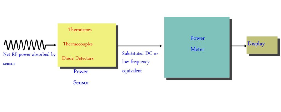
Steps and devices to measure RF Power. Courtesy of Evans.
Two Types of Radio Frequency Sensors
1. Diode Detector Based Radio Frequency Sensors
These types of sensors are designed with diodes as rectifiers that produce signal output. The RF power is dissipated by a load and the resulting voltage difference across the load is rectified by a diode detector. The result is then interpreted to measure the amount of power that went into the load. In practice, these sensors are used in analog power meters (which are typically lower power) as well as high power level meters. Specifically, these sensors have some advantages over other types of heat-based sensors.
Diode based sensors are very sensitive and can measure extremely low power levels, even going down to the -70 dBm range. Another strong point is that they have very fast response time, the reason being that their output can be processed through digital signal processing techniques. This means that the results can be given by choice: instantaneously, or set to be integrated throughout a certain time period.
The choice of diodes are another important factor in designing accurate radio frequency sensors. One excellent choice of diodes are metal semiconductor diodes, such as Schottky Barrier Diodes and Gallium Arsenide diodes. Because typical diodes store charge, they can limit the range of detection. However, metal semiconductor diodes by nature store only small amounts of charge and require small levels of voltage to conduct current.
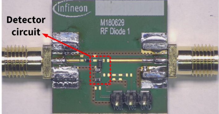
Photo of the evaluation board for BAT62-02V, BAT63-02V single diode detector sensor circuit. Courtesy of Infineon.
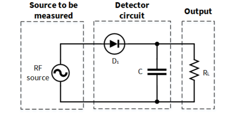
Schematic diagram of a single diode detector circuit. Courtest of Infineon.
2. Heat-Based Sensors
In contrast to diode detector sensors, heat-based sensors work by measuring the temperature (heat) rise after dissipating the power in the load. In spite of not being able to give instantaneous response like diode detector sensors, heat-based sensors have their own set of pros. For example, they give the true average power in the load due to the equation for heat: Q = ∫ P dt, where P is power, t is time, Q is heat. This integral means that we can find Power regardless of the waveform it’s given in, even more complex ones. Recently, complicated waveforms and modulation techniques have been coming into usage such as QAM, so heat-based sensors are the first choice in those cases.
There are two main types of Heat-based Radio Frequency Sensors. First, Thermistor power sensors have the advantage that RF Power can be substituted by DC Power to calibrate the sensor. How they operate is called the “balanced bridge technique.” For reference, thermistors themselves are semiconductors. In this technique a bias DC voltage is given to the thermistor, which is maintained at a constant resistance. When the RF power is dissipated and the temperature rises, the resistance will lower. This in turn requires the bias DC voltage to lower to maintain the balance of the bridge. Finally, the bias voltage difference indicates how much power was in the load. Thermistor sensors are usually designed in pairs to prevent errors in temperature readings that may result from the environment.
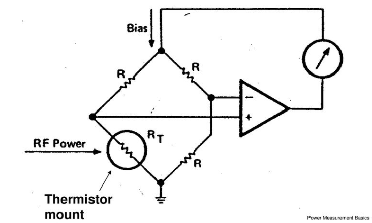
Self balancing bridge containing a Thermistor.
Courtesy of Evans.
The second type is called Thermocouple Radio Frequency Power Sensor. It has advantages over Thermistor sensors given its sensitivity to low power levels (~ mW) and sturdiness. How they work is through their junctions which contain various kinds of metals, and by their square-law detection characteristic. When the temperature rises after RF power is dissipated, DC electric potential will proportionally form at the junctions. Additionally, many Thermocouple sensors can be fit onto one silicon circuit chip.
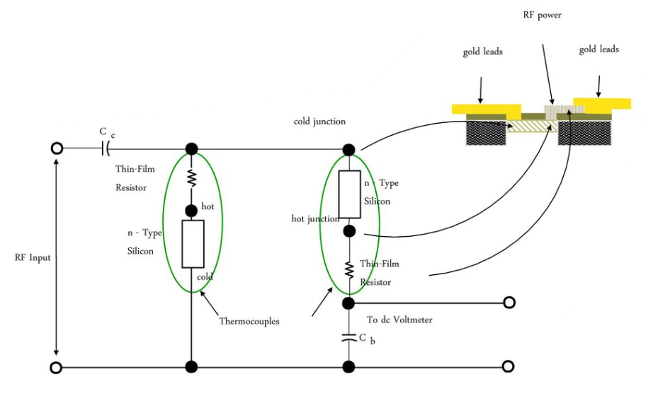
Diagram of paired thermocouple implementation. Courtesy of Evans.
Conclusion
Radio frequency sensors are crucial components to many different modern day industries such as process engineering, software app monitoring, chemical plants, irrigation projects, military intelligence, and aerospace. There is recent research going into using Radio Frequency sensors in smart systems for unmanned Aerial vehicles [1]. Along with that, radio frequency sensors and systems are cheap and easy to make. Hence they continue to be the main form of communications for longest distances (even from space to Earth). As there is still a large part of the spectrum being unused, and with exciting new advancements like 5G and smart systems, radio frequency systems/sensors prove to be a promising field to propel our society into the future. The dawn of the new age of smart cities and cars is just around the corner.
Further Reading:
