Description
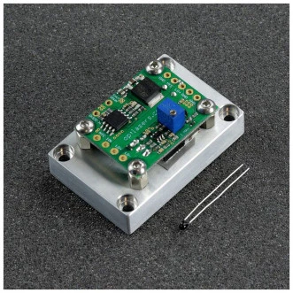
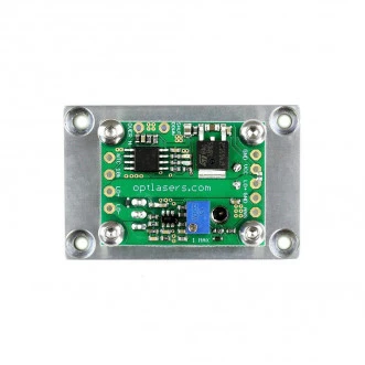
The LPLDD-5A-24V-TP-H Laser Diode Driver from Opt Lasers is a high-performance, versatile driver designed for a wide range of laser diode applications. Supporting an input voltage range of 7.5V to 35V, including standard 12V and 24V supplies, this driver ensures flexibility across various setups. It delivers a maximum output current of 5A and supports modulation frequencies up to 100 kHz, making it suitable for both continuous-wave and pulsed operations.
Engineered with thermal protection, the driver safeguards laser diodes against overheating, enhancing safety and operational reliability. It also supports multiple modulation modes, including TTL, analog, and combined modulation, providing users with precision control over laser output.
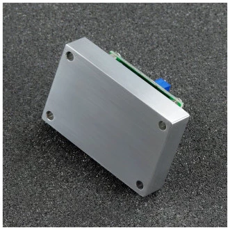
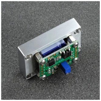
The -H version comes equipped with an additional heatsink, enabling efficient cooling, easier installation, and improved longevity of both the driver and the connected diode. Compatible with a wide range of laser diode wavelengths (405 nm, 445 nm, 520 nm, 638 nm, 650 nm, 808 nm, 980 nm), the LPLDD-5A-24V-TP-H is a robust and adaptable solution for laboratory, industrial, and research applications.
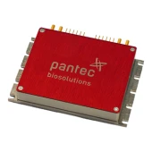
LPLDD-5A-24V-TP-H Laser Diode Driver
Specifications
| Single Channel: | 5 A |
|---|---|
| Laser Diode Driver With Thermal Protection: | 3.3 - 24 V |
| Minimum Current: | (3% Noise) 500 mA |
| Temperature Sensor Type: | 10k NTC thermistor |
| Modulation Type: | Analog |
| Rise Time: | less than 1.5µs |
Features
- Wide Input Voltage Range: Operates from 7.5V to 35V for versatile power supply compatibility.
- High Current Capability: Supports up to 5A continuous output for powerful diode operation.
- Flexible Modulation: Offers TTL, analog, and combined control modes with up to 100 kHz bandwidth.
- Thermal Protection: Built-in system prevents overheating, ensuring diode safety and longevity.
- Additional Heatsink (-H Version): Improves cooling efficiency and simplifies installation.
- Low Noise and Fast Response: Features short rise/fall times (<1 µs) with excellent stability.
Applications
- Laser Engraving & Cutting Systems: Provides stable and precise diode driving for industrial processes.
- Optical Research & Development: Suitable for laboratory experiments requiring accurate modulation.
- Medical & Biophotonics Equipment: Ensures reliable laser operation in sensitive diagnostic systems.
- Testing & Measurement Systems: Ideal for driving various diode wavelengths with consistent output.
- Prototyping & Custom Projects: Flexible driver for engineers and developers working with diode lasers.
Frequently Asked Questions
What is the input voltage range of the LPLDD-5A-24V-TP-H?
What is the maximum output current supported?
What modulation options are available?
How does the thermal protection system work?
What wavelengths are compatible with this driver?
Similar Products




Your inquiry has been received.
Create an account by adding a password
Why create an account?
- Auto-complete inquiry forms
- View and manage all your past messages
- Save products to your favorites
- Close your account anytime — no hassle
